Matthew Beckler's Home Page
:: :: :: :: :: ::
Java Heat Map
Convert Cadence Layout to SVG / PDF / PNG
Makefile -jX setting: How many concurent jobs is optimal?
Infinite Grid of Resistors
How to Start and Stop Folding@Home on OSX
Lego Rendering with POV-Ray
Class Scheduler
Lightsaber Rotoscoping Scripts

Handy Scripts
GPG Tips and Tricks
NCAA Basketball Tournament Data

Isometric Projection in Inkscape
Perspective Motivational Poster
SVG Drawings
SVG Circuit Symbols
Mysterious Textures
Fun with an RGB LED
Abstract: I picked up a cheap RGB LED from RadioShack (276-028) on my way home from school/work yesterday. I recently built an Arduino so I thought that using this RGB LED with PWM output would be a fun way to get introduced to the Arduino way. Using three external potentiometers, I was able to mix different proportions of red, green, and blue in the same LED, producing nearly any color imaginable.
General Description: The Arduino is a pretty slick platform for microcontroller development based on the Atmel line of microcontrollers. The system comes with some convenient functions for initialization and operation, that really help decrease the development time for most projects. For this little project, I want to connect a tri-color RGB LED to the microcontroller with PWM ("analog") outputs to control the brightness of each color, and use three analog inputs to set each color's brightness.
More Details (Tri-color RGB LED's): An RGB LED is simply three separate LEDs crammed into a single 5mm LED package. There is one each of red, green, and blue LED element. These three LEDs share the same positive (anode) terminal, which means that this RGB LED has a "common anode" connection. To control each color, simply connect its cathode pin to ground (usually through a resistor), and it will light up. Be sure to use current-limiting resistors to protect the LEDs from burning out, and you can also use pulse-width modulation (see below) to change the brightness of an LED. Since RadioShack forgot to include a pin-out with the packaging for this LED, I've drawn up the correct pin-out here:
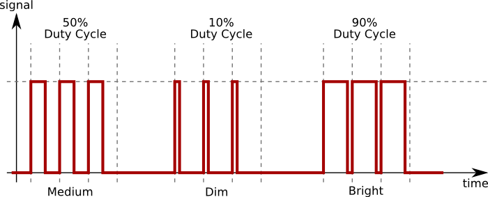
More Details (Pulse-width Modulation): The brightness of an LED is proportional to the current going through it, but it would be rather difficult to use a microcontroller to accurately control the current flowing through an LED. Fortunately, human vision has a nice phenomenon called persistence of vision. Persistence of vision is the phenomenon where an image that is seen for only a fraction of a second will continue to be "seen" by your brain even after the original image has vanished or moved. This this the same principle behind film and television, where a rapidly changing image tricks your brain into seeing continuous motion. By turning our LED on and off rapidly, we can trick the brain into seeing an "average" value of brightness based on the duty cycle of the driving PWM signal.
Pulse-width modulation (PWM) is the practice of modulating the duty cycle of a signal, used in this application to control the average power sent to each LED. In the following figure, we show three different duty cycles, first with 50% duty cycle, then 10% and 90% duty cycle. During the 10% duty cycle, the signal is at the logic high level for only a brief time each cycle, but with 90% duty cycle, most of the signal's period is spent at logic high level. If the frequency of the signal is fast enough, then there will be no visible flicker, and the LED's brightness will be proportional to the signal's duty cycle.
Circuit Schematics: The circuit is divided into two sections, the Input and Output sections. The input circuit has three potentiometers, which are simply variable resistors. For this application, we are using the potentiometers to produce a controllable analog voltage by connecting the potentiometer's ends to power and ground, and connecting the third terminal (the "wiper") to the analog input pin. When we turn the potentiometer, the measured voltage will vary between ground and power (here, 5 volts). There are three potentiometers, one for each color, and are connected to the Arduino's analog inputs 0, 1, and 2, corresponding to red, green, and blue.
The output circuit has the LED's common anode connected directly to power (also known as Vdd). The cathode pin of each color is connected through a current-limiting resistor to one of the digital output pins on the Arduino. The current-limiting resistors are used to protect the LEDs from over-current situations, and if you want more information about driving LEDs with and without resistors, there is a good guide at the Tinkerlog website. We use the Arduino's pins 9, 10, and 11 specifically because these pins are able to do PWM output, via the analogWrite() function. This allows us to set the brightness for each color independently.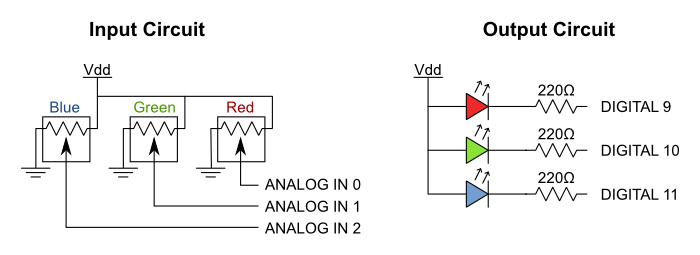
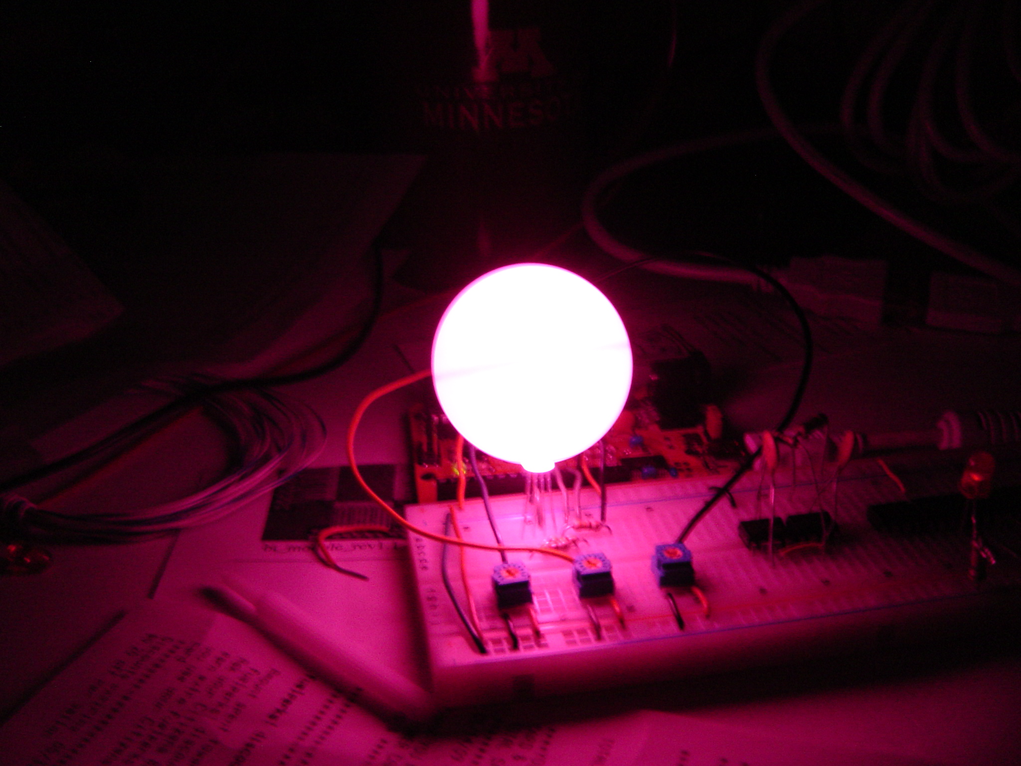
Results: This project turned out quite nice. I cut a small hole into a ping pong ball, which I then placed over the LED, to act as a light diffuser. This made the light much more uniform with fewer spots of individual, un-mixed color. I created a little color-shifter program to cycle through lots of different color combinations, and recorded a video shown below.
Source Code: There are two programs to download here. The first is for the project where you use the three potentiometers to control the output color of the RGB LED. The second program ignores the potentiometers and simply cycles between colors over and over again.
Download source code for potentiometer-controlled LED
// RGB LED - Color Control With Potentiometers
//
// Matthew L Beckler
// matthew at mbeckler dot org

int redPin = 11;
int bluePin = 10;
int greenPin = 9;

int redIn = 0;
int greenIn = 1;
int blueIn = 2;

int redVal;
int greenVal;
int blueVal;

void setup()
{
  // nothing to do here
}

void loop()
{
  redVal = analogRead(redIn);
  greenVal = analogRead(greenIn);
  blueVal = analogRead(blueIn);

  // analogRead returns a value between 0 and 1023
  // analogWrite wants a value between 0 and 255
  // That means we need to map the input range to
  // the correct output range.
  redVal = map(redVal, 0, 1023, 0, 255);
  greenVal = map(greenVal, 0, 1023, 0, 255);
  blueVal = map(blueVal, 0, 1023, 0, 255);

  analogWrite(redPin, redVal);
  analogWrite(greenPin, greenVal);
  analogWrite(bluePin, blueVal);
}
Download source code for color-cycling LED
// RGB LED - Automatic Color Cycling
//
// Matthew L Beckler
// matthew at mbeckler dot org

int redPin = 11;
int bluePin = 10;
int greenPin = 9;

int redIn = 0;
int greenIn = 1;
int blueIn = 2;

int redVal;
int greenVal;
int blueVal;

void setup()
{
  redVal = 255;
  greenVal = 255;
  blueVal = 255;
  update();
}

// This function updates the LED outputs.
void update()
{
  analogWrite(redPin, redVal);
  analogWrite(greenPin, greenVal);
  analogWrite(bluePin, blueVal);
}

// This function updates one of the color variables
// either getting brighter or getting dimmer.
// It also updates the outputs and delays for 10 milliseconds.
void color_morph(int* value, int get_brighter)
{
  for (int i = 0; i < 255; i++)
  {
    if (get_brighter)
      (*value)--;
    else
      (*value)++;

    update();
    delay(10);
  }
}

void loop()
{
  // start out at black (all off)
  color_morph(&redVal,   1); // transition to red
  color_morph(&greenVal, 1); // transition to yellow
  color_morph(&redVal,   0); // transition to green
  color_morph(&blueVal,  1); // transition to aqua
  color_morph(&redVal,   1); // transition to white
  color_morph(&greenVal, 0); // transition to violet
  color_morph(&redVal,   0); // transition to blue
  color_morph(&blueVal,  0); // transition to black (all off)
}


Copyright © 2004 - 2026, Matthew L. Beckler, CC BY-SA 3.0
Last modified: 2009-10-23 06:04:12 PM (EDT)