Archives

All posts by Matthew

At my dayjob I often listen to music while working, and sometimes I’m doing video calls with my team. To help avoid disruption, I put an RGB LED on top of my cubicle wall and wrote a script to update the color based on my activity. Red indicates the camera is active, amber indicates I’ve got music going, otherwise green.

#!/bin/bash
#
# Monitor the camera and audio to set LED color
# if camera active --> RED
# else if audio active --> YELLOW
# else --> GREEN

exec 2> /dev/null

COLOR_OLD="#ABCDEF"
while :
do
  COLOR="#00FF00"
  if lsof /dev/video0 > /dev/null ; then
    COLOR="#FF0000"
  else
    AUDIO=`pacmd list-sink-inputs | grep -c 'state: RUNNING'`
    if [ "$AUDIO" == "1" ]; then
      COLOR="#FFAA00"
    fi
  fi

  # Only update blink1 if the color has changed
  #echo "\"$COLOR\" vs \"$COLOR_OLD\""
  if [ $COLOR != $COLOR_OLD ]; then
    echo "Color: $COLOR"
    blink1-tool --rgb "$COLOR" > /dev/null
    COLOR_OLD=$COLOR
  fi

  sleep 0.1

done

Just wanted to add this datapoint to the world. My Lenovo Thinkpad Carbon X1 Gen 11 Linux Edition, running the pre-installed Ubuntu 22.04, is working great with this Lenovo USB-C dock:

“ThinkPad Universal USB-C Dock v2” https://www.lenovo.com/us/en/p/accessories-and-software/docking/docking_usb-docks-(universal-cable-docks)/40b70090us

They seem to refer to these dozens of different types of docks by the first four digits of the product number, which is 40B7 here.

This morning I easily started running a Tor Snowflake relay on my home server, and wanted to share my experience in case anyone has bandwidth to share to help out folks with censored internet. This is not running an “exit node”, where onion-routed traffic leaves the Tor network and hits the public web servers (which can cause troubles with your ISP), but rather an encrypted-to-encrypted bridge in the routing network. If you want to stick it to Russia, Iran, China, and anyone else stifling free speech of their own residents via censored internet, this is an easy way to help.

$ cat docker-compose.yml
version: "2"

services:
snowflake-proxy:
network_mode: host
image: thetorproject/snowflake-proxy:latest
container_name: snowflake-proxy
restart: unless-stopped
command: ["-verbose", "-unsafe-logging", "-summary-interval", "1m"]
$ docker-compose up -d snowflake-proxy


I took their default docker-compose file and changed the version to 2, which is the latest that my old server’s docker supports. I also added the command line to get some debugging logs to make sure it’s working right. Here’s how you check those logs to make sure you’re getting relay connections:

$ docker logs snowflake-proxy
...
2022/10/04 13:54:09 In the last 1m0s, there were 5 connections. Traffic Relayed ↑ 53 MB, ↓ 4 MB.
...

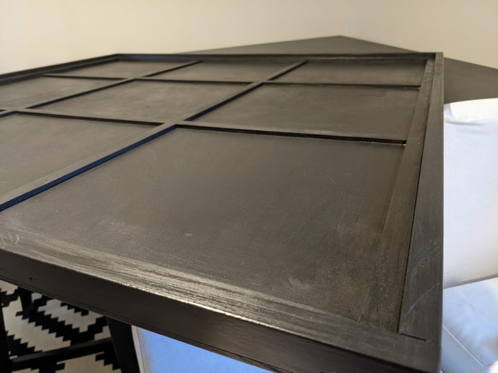
With two cats, it’s difficult to have a puzzle sitting out on a table in-between actively solving it. At least if you want the puzzle pieces to stay on the table :-)

When we received a really nice, new-to-us high-top table that would be just perfect for board games and puzzles, I designed a lightweight cover for the table that would keep the puzzle pieces safe from the cats. Here’s the initial design I sketched up:

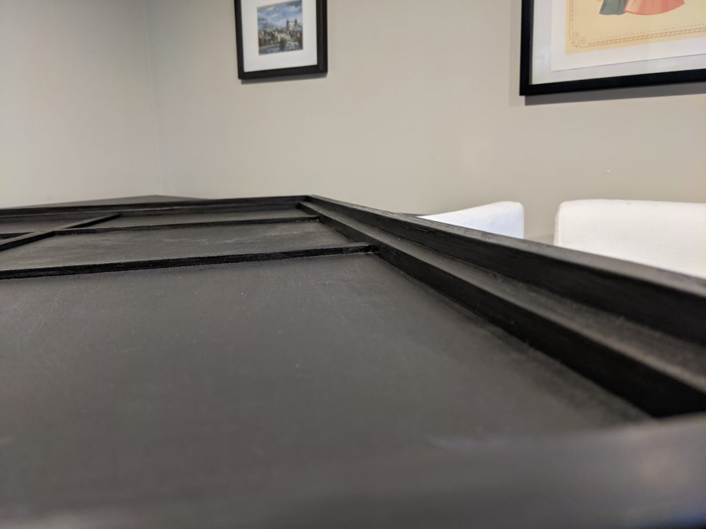
The design above is a side-view cross-section, showing the table top itself, plus the multi-piece cover, consisting of a plywood top and two pieces of dimensional lumber to keep the cover from falling off and also to keep it elevated above the puzzle pieces.

I hired my amateur-woodworker brother to build the lid, and it turned out great!

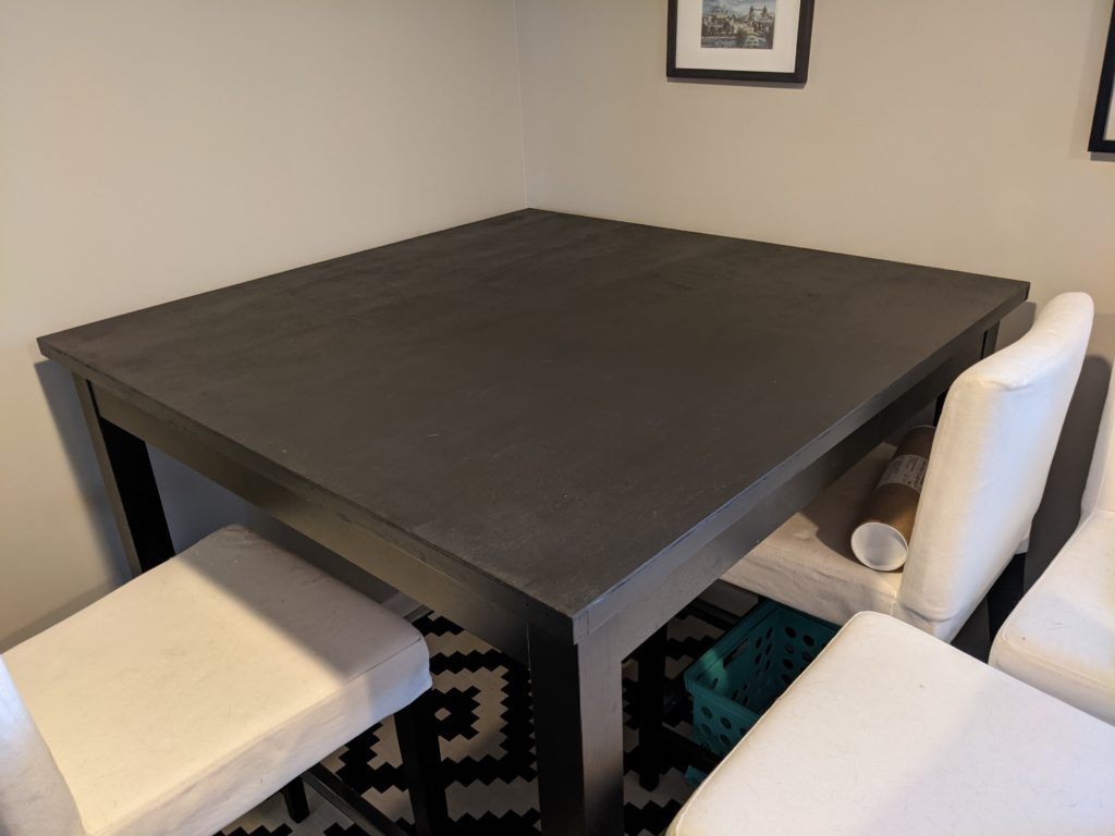
The finished lid matches the rest of the table so well you hardly notice it’s there.
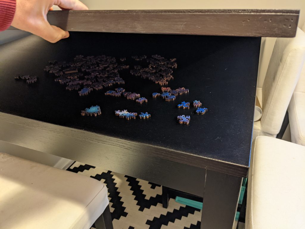
Lift off the lid, and surprise! Puzzle pieces are secretly protected from cats.
Upside-down view – Jeremy used 5mm plywood, and added thin supports underneath the top
Here we can see the cross-section. The corner piece around the outer edge supports the cover above the puzzle pieces so they are not disturbed.

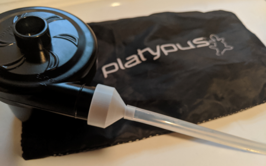
I just returned from a trip into the Boundary Waters Canoe Area Wilderness (BWCA) where we had good luck using my Platypus gravity water filter to easily produce safe water for drinking and cooking. When I return home from such a trip, I want to clean, disinfect, and dry out the bags and hoses to get them ready for the next expedition. I’ve often thought that it would be useful to have a source of high-volume, low-pressure airflow for drying out these sorts of things (also beer brewing equipment and hoses), but now I’ve finally found a good solution.

I realized that the little inflator for our air mattress would be a great source of airflow, and that I could probably 3D print a set of adapter nozzles for each type of hose I want to dry out. Here’s the first adapter, for my Platypus filter hoses.

The design is in Open SCAD, a free and open source parametric 3D modeling program that works great for simple geometric models. Once you install OpenSCAD you can copy/paste this code into OpenSCAD and build the model and export an STL. Hopefully you should be able to customize the sizes to adjust for a differently-size blower output or hose diameter:

// units = mm
$fn=64;

// blower output is 25mm diameter, 12mm along shaft
// platypus hose ID is 6mm but the filter barbs are 8.9mm, so... 7mm?

// Design intent:
// Build an outer union and subtract a similar but smaller inner union
// Each union is two cylinders connected by a sloping cylinder:
// AAAB
//     B
//      B
//       BCCC
//
//       BCCC
//      B
//     B
// AAAB

// Some variables to adjust the design
wide_ID = 25; // Wide end, inner diameter
wide_OD = 30; // Wide end, outer diameter
narrow_ID = 4; // Narrow end, inner diameter
narrow_OD = 7; // Narrow end, outer diameter
wide_h = 12; // Wide end height before angled part
angled_h = 12; // Angled part height
narrow_h = 6; // Narrow end height before angled part

difference() {
    // outer part
    union() {
        cylinder(h=wide_h,d=wide_OD);
        translate([0,0,wide_h])
            cylinder(h=angled_h,d1=wide_OD,d2=narrow_OD);
        translate([0,0,(wide_h + angled_h)])
            cylinder(h=narrow_h,d=narrow_OD);
    };

    // inner part to be subtracted
    union() {
        translate([0,0,-1])
            cylinder(h=(wide_h + 1),d=wide_ID);
        translate([0,0,wide_h])
            cylinder(h=angled_h,d1=wide_ID,d2=narrow_ID);
        translate([0,0,(wide_h + angled_h)])
            cylinder(h=(narrow_h + 1),d=narrow_ID);
    };
};

If you add a # before the union for the inner part to be subtracted, the OpenSCAD interface will show that component in translucent red:

Render the design (F6 key) and export to STL (F7 key), then slice and print.

You may need to adjust the parameters to obtain a perfect fit with your specific equipment.

I have a small linux server at home, chiefly for file storage and running a plex server. In the past, I’ve used a Linux software RAID-1 (mirror) of two drives to provide more-robust storage for important files (documents, photos, etc), and a single drive for media files (that could be re-backed-up from their original CD/DVD media, if lost). Recently I wanted to transition to a combined ZFS storage array for everything, for the following reasons:

  • Filesystem checksums (during normal read/write operation, plus weekly scheduled full-array scrubs) to ensure that there is no “bit rot” where files silently change over time.
  • Full mirroring protection of all files
  • In-place expansion capability

Research references

After discussions of my needs and capabilities with a ZFS “expert” friend, here’s the plan I decided to go with:

  • Create a single ZFS pool (top-level filesystem)
  • This ZFS pool will consist of two virtual device (VDEVs in ZFS parlance), where each VDEV is a “mirroring” VDEV, where all drives in each VDEV are mirrored with each other, providing RAID-like drive redundancy within each VDEV.
  • Set up cron jobs to periodically scrub the ZFS pool to verify the checksums and ensure the pool is in good health.
  • Initially set up 2x 4TB drives in one VDEV, and 2x 2TB drives in the other VDEV, resulting in 6 TB total storage in the pool.
  • When more space is required:
    • Add 2x larger drives to the smaller VDEV
    • Wait for the VDEV to resilver [1]
    • Remove the smaller drives from the VDEV
    • Expand the VDEV to the size of the new larger drives

To help plan this out, and learn the ZFS terminology, I created a series of statements about ZFS:

  1. A ZFS pool is made from one or more virtual devices (VDEV), which are, in our cases, 2+ physical drives mirrored together.
  2. A ZFS pool expands when its existing VDEVs become larger, or by adding another VDEV, but you can never remove a VDEV from a pool (but you can *replace* a VDEV, which is swapping one VDEV out for another, using zpool replace).
  3. You can add a new drive to a mirroring VED and it’ll “re-silver” and add that new drive to the mirroring, slowly over time.
  4. You can remove a drive from a mirroring VDEV and it keeps going. Of course, if you remove the last drive of a mirroring VDEV, it can’t keep going.
  5. An autoexpand=on mirror VDEV expands when all the member drives are large enough. Or turn off autoexpand and do it manually using online -e
  6. zpool replace lets you switch the internal architecture of the VDEV (like switch from RAIDZx to/from mirror). If you just add new big drives to the existing VDEV, let them recover, and then remove the old smaller drives, it of course stays as a mirroring VDEV.

Here are the commands used to build, maintain, and expand the ZFS pool:

  • Create the zpool from two mirrors of two drives each:
    • sudo zpool create mypool mirror /dev/sda /dev/sdb mirror /dev/sdc /dev/sdd
    • Note: The command above uses the /dev/sdX device names, which may changed based on device initialization order at boot time, so it’s strongly suggested to instead use the device files in /dev/disk/by-id/ which will not change.
  • Create the ZFS filesystem mount point in the zpool:
    • sudo zfs create mypool/zfs
  • Set the mountpoint:
    • sudo zfs set mountpoint=/whatever mypool/zfs
    • Note that you don’t need to put anything into /etc/fstab for this ZFS pool mountpoint, it’ll be mounted automatically when ZFS starts up at boot.
    • I don’t know how to use ZFS for your boot drive (/) as I only use it for non-OS data.
  • Add an optional drive for ZFS intent log:
    • sudo zpool add -f mypool log /dev/nvme0n1
    • A friend loaned me a nifty PCIe SSD to experiment with, so I added it to store my ZFS intent log (much like the EXT journal). I don’t think my typical “frequent-read with rare-writes” workload really take advantage of this cool device, it was mostly a fun experiment.
  • Add these entries to root’s crontab with sudo crontab -e:
    • # Every Monday at 00:00, start a ZFS scrub
      0 0 * * 1 /sbin/zpool scrub mypool
      # Every Monday at 18:00 (6pm), send the zfs zpool status email
      0 18 * * 1 /sbin/zpool status
  • When we want to upgrade the 2 x 2 TB drives to 2 x 4 TB drives:
    • The syntax here is somewhat odd. We attach each new drive to one of the old smaller drives, which is how the new drives get added to the mirror.
    • sudo zpool attach mypool -f oldDriveName1 newDriveName1
      sudo zpool attach mypool -f oldDriveName1 newDriveName2
    • Use sudo zpool status to monitor the resilvering process. You should see that the VDEV with the smaller drives now has the newly-added larger drives.
    • Once resilver is complete, run a scrub (just in case), to confirm everything is working right and your data is safe.
    • Remove the old drives:
      • sudo zpool detach mypool oldDriveName1
        sudo zpool detach mypool oldDriveName2
    • Expand the new drives:
      • sudo zpool online -e mypool newDriveName1
        sudo zpool online -e mypool newDriveName2
    • You can now use sudo zpool list or df -h to see that the pool has expanded in size, and now you can store more data!

Hope this helps! Feel free to leave a comment if you notice any typos, or have any suggestions to add.

[1]. To “re-silver” is what you’d do to an antique mirror when it became degraded and needed to be restored :-)

I have had a few pairs of Koss SB-49 over-ear headphones. They sound good and are very comfortable, and are pretty inexpensive too (maybe $30-40). I’ve had several pairs over the past decade, and the most-frequent failure point is the cable, either developing a short or disconnect, or the cable getting brittle and cracking around the underlying wires.

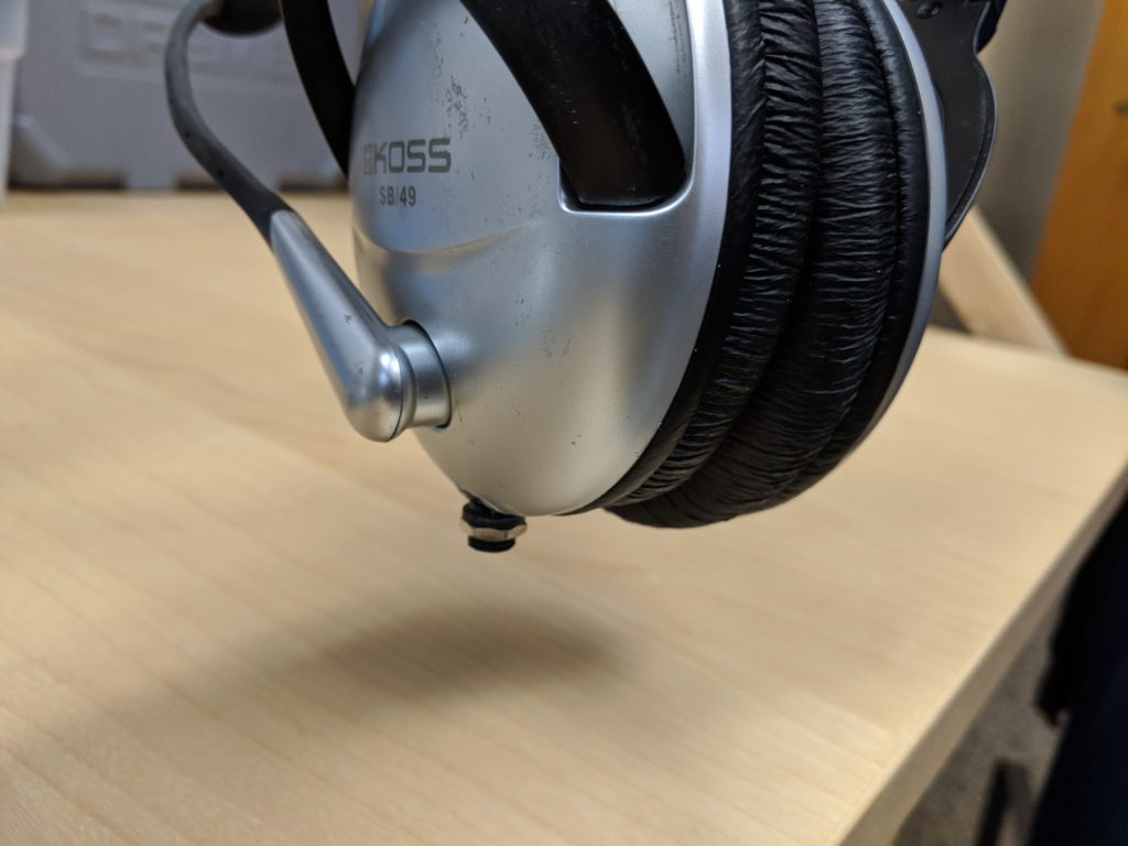
I recently fixed my latest pair of headphones by removing the cable and replacing it with a TRRS socket. I’ll have to use a separate cable to connect the headphones to a computer/MP3 player, but it means that when the cable breaks I can simply get a new cable and plug it in.

Results

Here’s the finished repair. Looks pretty good, right?
Repair process

To start with, I had to figure out how to open up the left-side headphone, where the current cable is attached. After lots of futzing, I removed the soft ear padding part by sliding it off very carefully. However, it turns out that this is not necessary, if you know where the hidden screws are located. In the image below, you can see me sliding the inner foam away to expose a screw hole. Use a small phillips screwdriver to remove the three screws (one indicated below, and two on the opposite side on both sides of the cable entry point).
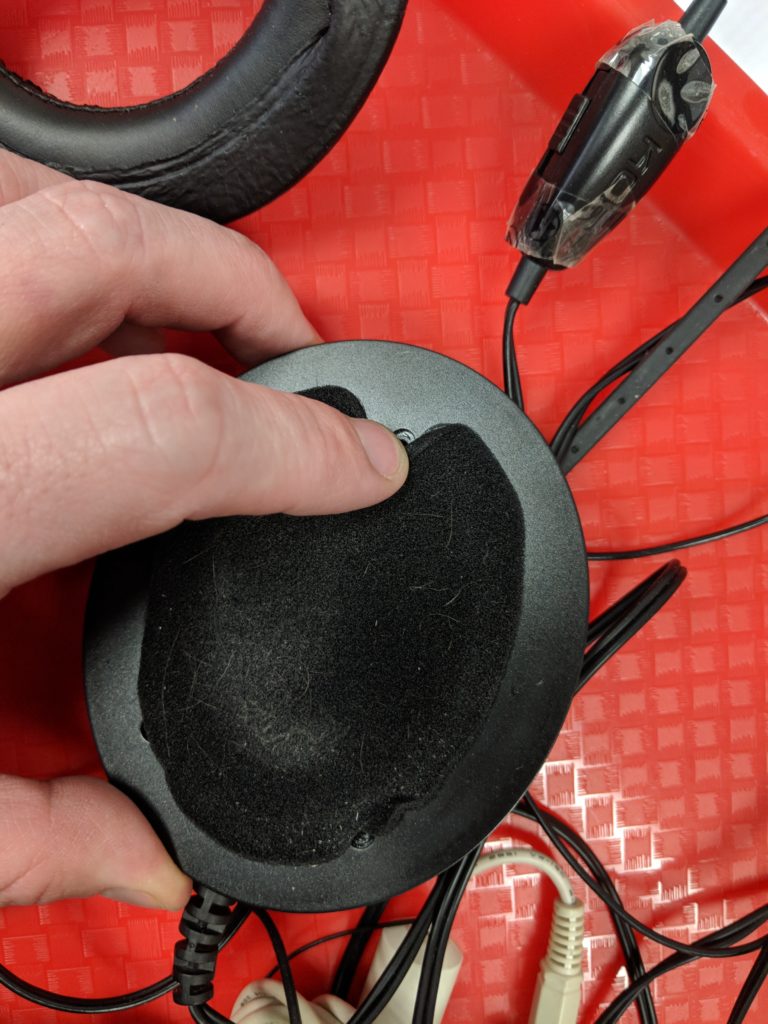
Peel back the foam covering a bit to expose the three screw holes (one by the finger, two below by the end with the to-be-removed cable).

You can also remove the two screws on the headband to disconnect the cup from the headband (aside from the small wire going to the right-side headphone), but I don’t think this is necessary.

Once the cup is open we can inspect how the wires are connected to the two speakers and the microphone. My notes are shown below, but there are basically two cables entering the left headphone. The first is the speaker cable, which has red, blue, and bare copper wires inside. The bare copper wire is the “shield” connection on the TRS speaker plug, and is connected to both speakers as the common return path. The blue wire is connected to the left speaker, and the red wire is connected to the right speaker. The microphone cable has two conductors, the bare copper common wire and the mic signal in the white insulation.

Since my laptop and phone both have a four-conductor TRRS (Tip-Ring-Ring-Shield) cable socket, I decided to add a single TRRS socket to the headphones, hopefully in the same hole where the old cable was. I purchased a few of the “Jameco Valuepro PJ31640 4 Conductor TRRS Panel Mount Phone Jack, 3.5 mm” sockets. I followed the newer CTIA standard for TRRS plugs:

  • Tip = socket pin 2 = left audio = blue wire
  • Ring = socket pin 3 = right audio = red wire
  • Ring = socket pin 4 = common ground = bare copper wires
  • Shield = socket pin 1 = microphone signal = white wire
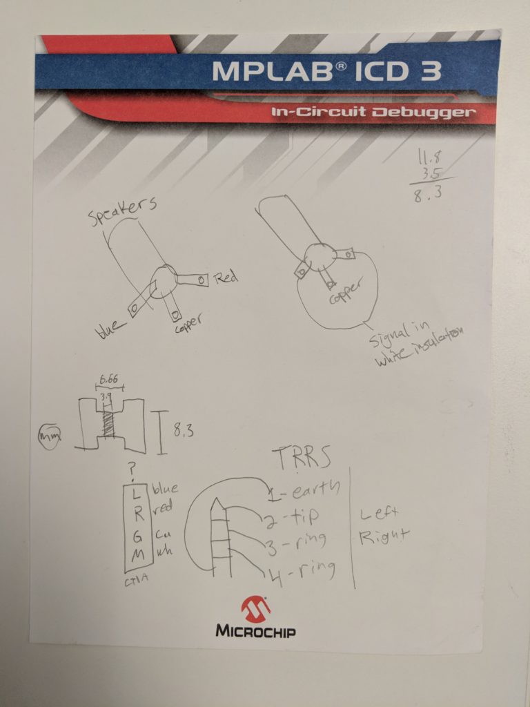
Notes about the connections between the speaker/mic plugs and the actual wires inside the left headphone. Below the “TRRS” heading, the word “earth” should really be “shield” as it’s used for the mic signal, not the common “earth” ground signal. (Ignore the drawing on the left side below the speaker wire diagram, it’s for a different project. Also ignore the simple subtraction in the upper-right corner.)

The next step was to cut the wires just past where they enter the headphone, to give us enough slack cable to work with. After deciding how to connect the four wires to the four pins of the TRRS socket (see plan above), we need to solder the wires to the socket pins. For the two bare copper ground signals (one for the speakers, one for the mic) I just soldered them both to the corresponding pin of the TRRS socket.

One thing to keep in mind when working with audio cables like this, is that the wires are typically coated with enamel, which will prevent you from soldering to it. You can quickly insert the tip of the enameled wire into a small flame to burn off the enamel, but be sure to blow-out the flame if the coating starts to burn.

I decided to add a bit of color-coordinated heatshrink tubing to ensure that the bare copper wire never made contact with any of the audio signals when everything gets jammed into the headphone and closed up. You can see two photos of that below.
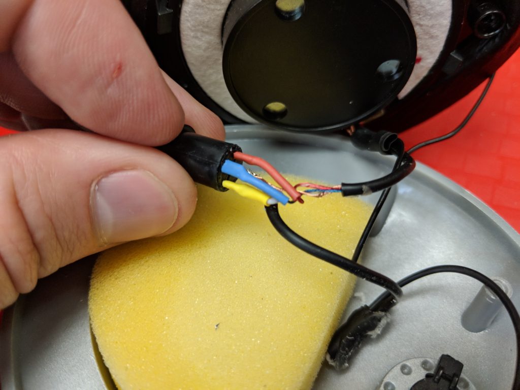
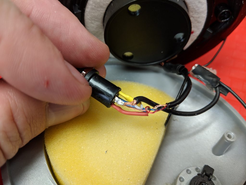
Closing the headphone

With this kind of “panel mount” socket, it has a threaded barrel and nut that are designed to pinch the socket onto a faceplate. However, there wasn’t enough room inside the headphone to slide the socket all the way in, so I decided that the easiest option was to leave it sticking further out. I needed to file down the opening a little bit to ensure the socket fit snug in the slot. I then applied lots of superglue around the barrel of the socket, to ensure it was firmly attached. I then screwed it back together, trying to avoid gluing the two halves together (even if they did, the glue would be on the removable ear pad, so that’s 1. replaceable, and 2. easy to remove even if it’s glued to the socket).
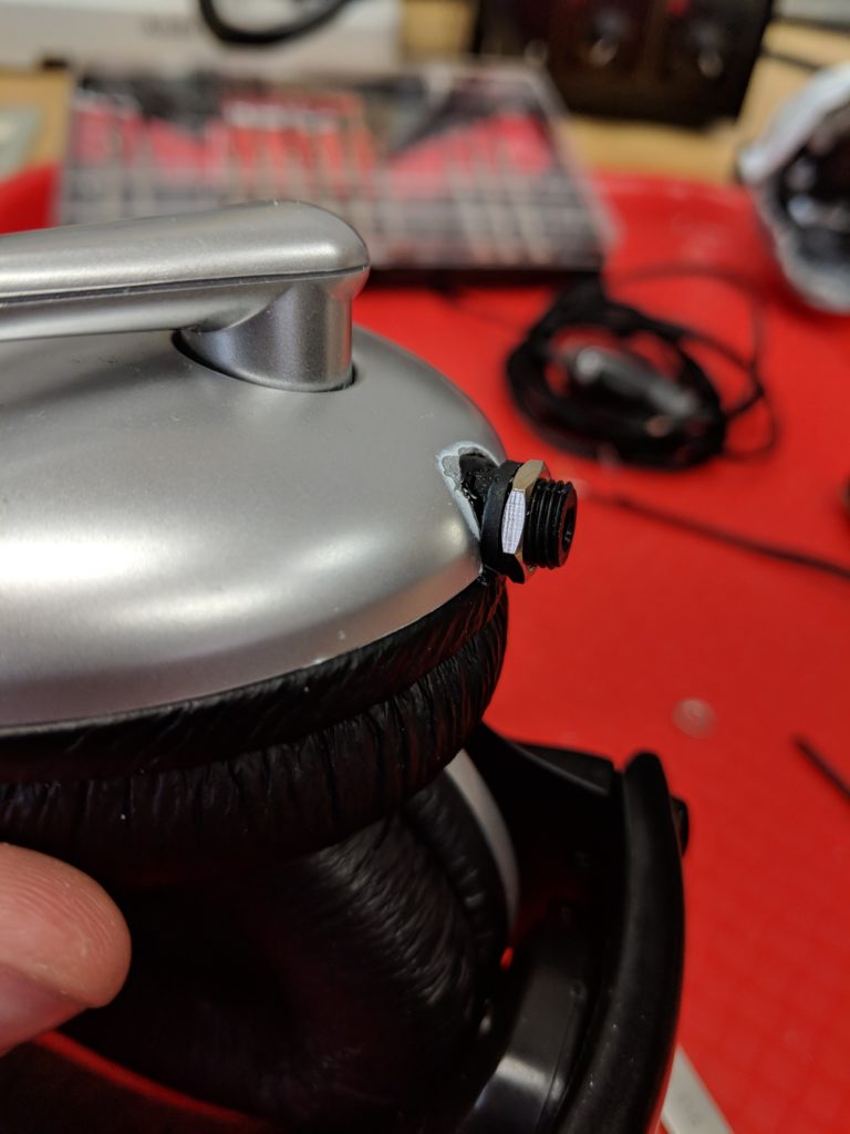
Normally the edge/face of the enclosure would be sandwiched between the metal hex nut and the extrusion of the black plastic socket that’s just to the left of the nut.
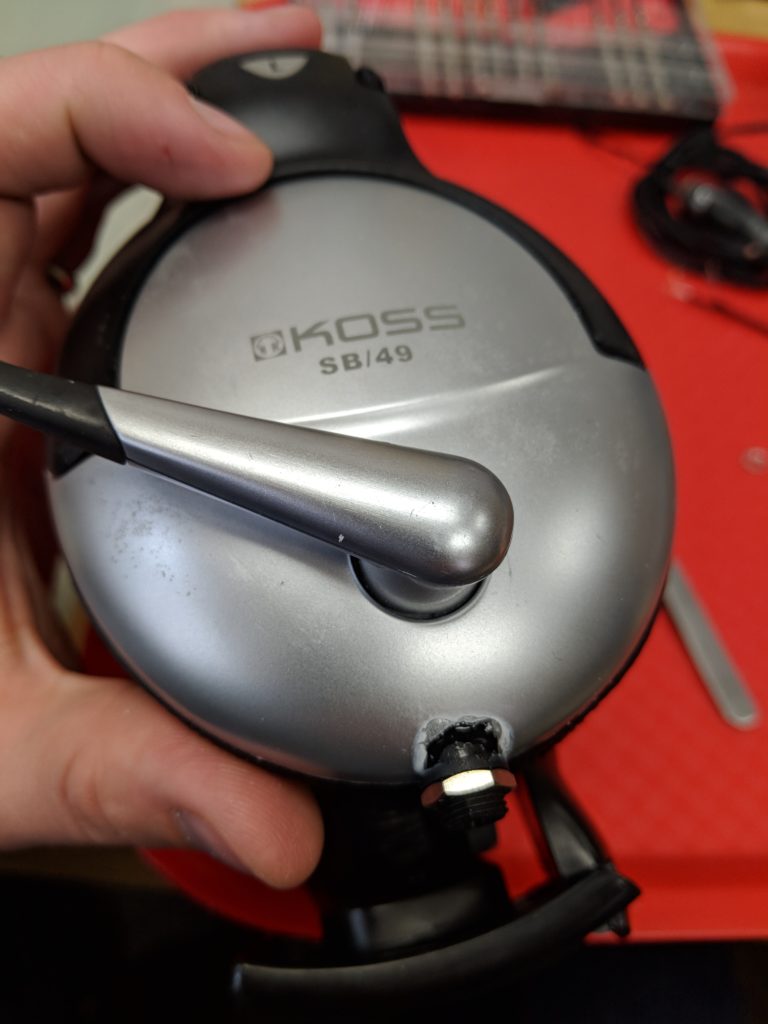
Superglue tends to deform and disfigure some types of plastic (see the white aura around the glue area) but I don’t mind.

Hope you find this interesting, and useful in case you need to make a similar repair of your own headphones someday!
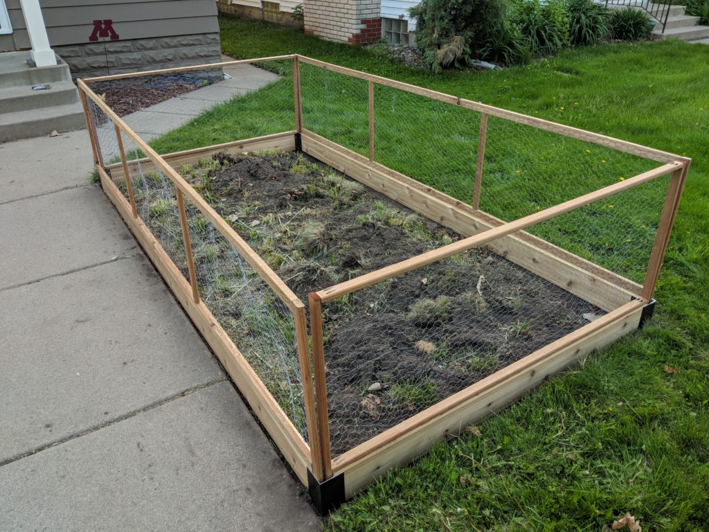
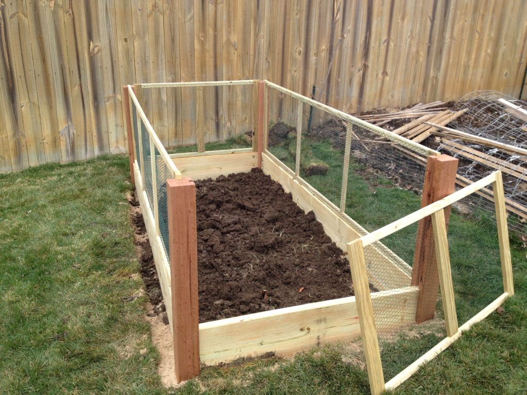
There are a ton of rabbits on our neighborhood, so we wanted to find an attractive way to keep them out of the garden. After a fall and winter with chicken-wire + four metal fence posts, we started researching different ways of building a slightly-raised garden bed with a well-supported fence around the outside. Additionally, we wanted the fence to be easily removed as needed for planting, weeding, cultivating, harvest, etc. Here’s the finished project:

Planning

After looking around at pinterest and various websites, we found three potential designs that might work:

Option 1 – Notched corner post with framed fence panels
Pros: Looks nice, would be sturdy, reasonable price.
Cons: Need to use table saw to cut channels in posts. Unsure how deep into ground to drive posts. If the posts shift over time, it may become difficult to slide the fence panels in and out.
Cost estimate: $147

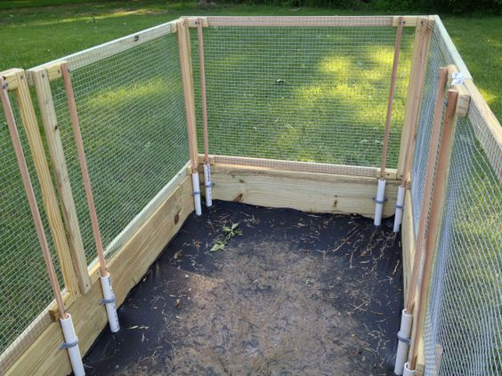
Option 2 – Normal frame plus PVC holders for fence panels
Pros: No expensive corner brackets or posts. PVC holders like this are widely-used and can be used with hoops+plastic to make a mini greenhouse.
Cons: More fiddly to build fence panels, need to keep tubes clear of dirt
Cost estimate: $132 (with 4×4 corners) or $106 (no corners, just screw 2×6’s together)

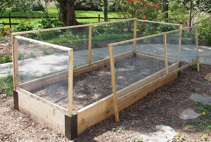
Option 3 – Pre-fab metal corners with fence panels that slide into holes in the corners
Pros: Metal corners would make it very sturdy and look very nice. Fence panels would be easy to keep square even if things shift around.
Cons: Metal corners are more expensive ($12.50 each from Gardener’s Supply Company)
Cost estimate: $145

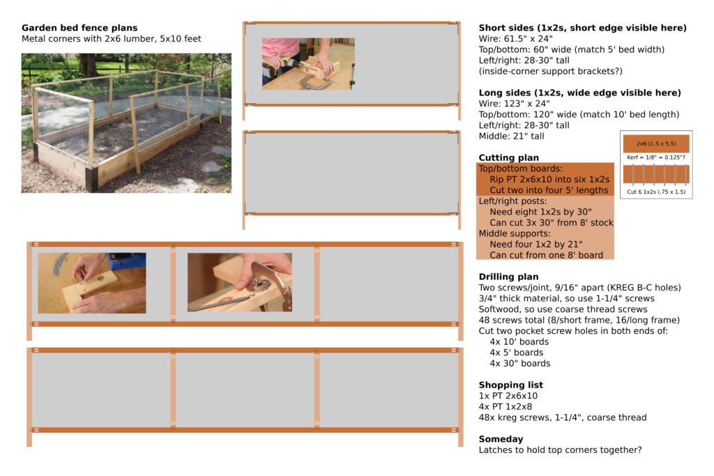
Since this garden bed is in our front yard, we really wanted it to look nice, so we chose Option 3, using the pre-fab metal corners to keep the bed nice and square, with drop-in fence panels. Here’s the detailed plan we came up with (click to view higher-resolution image):

In the past, I’ve wanted to experiment with pocket screws, and this seemed like a decent project for an experiment. I borrowed a Kreg jig from a friend, and bought a box of their blue outdoor pocket screws. (We decided not to use the extra support brackets shown in the plan.)

Results

For once, it turned out like the pinterest image! Nailed It!

Lessons learned

If I was to do this project again, I would make a few changes to the plan:

  • Design the bed to be 4×8′ instead of 5×10′, because it’s difficult to get 10′ lumber in all sizes and types. I wasn’t able to find pressure-treated 1x2s in 10′ lengths, so I had to rip a 2x6x10 into 1x2x10s using the table saw, which was tricky.
  • The pocket screws had a tendency to split the thin 1×2 boards. I may have mis-configured the drill jig, or maybe I should have pre-drilled the other board too, or maybe should have used the fine-thread screws instead of coarse-thread screws?
  • I still need to figure out some way to keep the upper corners of the fence panels together. Maybe a door hasp closure or some velcro or something.

I typically listen to music with only my left headphone at work, so I can hear what’s going on around me. It bugs me when I listen to music that has important parts split across left vs right audio channels. I found this trick with the linux pulseaudio system to make a new audio output device that is a mono-only output, so it mixes left and right together. Only tested on Ubuntu 14.04, so some things may be different with more recent Ubuntu versions.

1. Use pacmd list-sinks | grep name: to find the name of the output you want to use. Mine was alsa_output.pci-0000_00_1b.0.analog-stereo (strip away the < and >).

2. Use that string in this command: pacmd load-module module-remap-sink sink_name=mono master=alsa_output.pci-0000_00_1b.0.analog-stereo channels=2 channel_map=mono,mono

3. Use the GUI sound settings to select the new “Remapped Built-in Audio Analog Stereo”.

It doesn’t sound 100% as good as listening to the stereo music via both headphones, but it’s pretty good.

I decided to train for a marathon this fall, so I looked online for some training plans. Once I found a plan to use, I wanted an easy way to import the training plan into my calendar. I thought it might be cool to write a little tool to let me copy/paste from the training plan website and generate an ICS file to import into the calendar.

I wrote such a tool in python, posted here: https://github.com/matthewbeckler/training_plan_to_ics

You should customize the script by editing five things in the python file:

  1. Set a start_date or end_date below (but not both).
  2. Copy/paste the tab-split training plan table into the raw_data string.
  3. Then add day_of_week_details entries for each day of the week (if you want).
  4. If you want an URL added to the end of the details, add one to the url variable below.
  5. The output ICS file will be written to the file output_filename, change this filename if you like.

Once the script is run, you can import the ICS file into your calendar system.