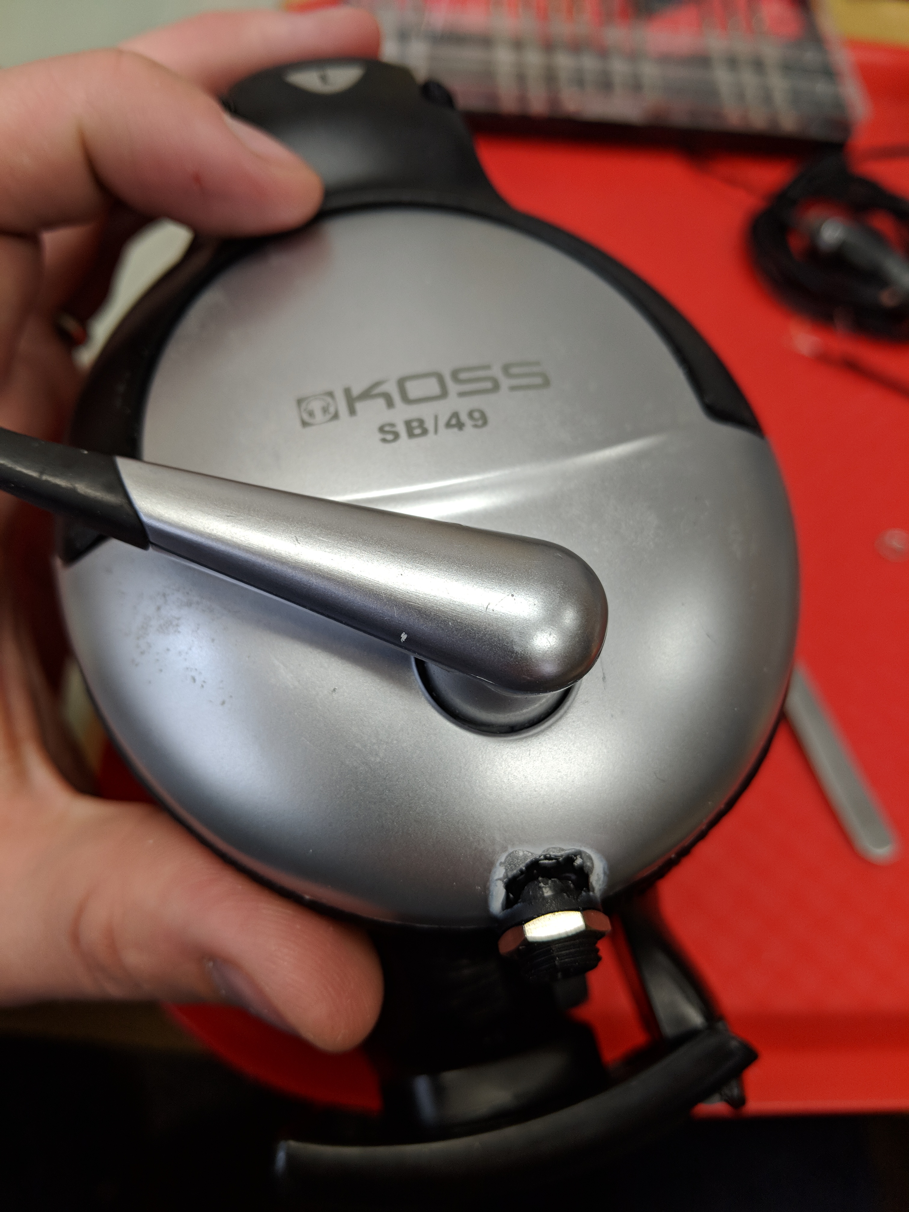
I have had a few pairs of Koss SB-49 over-ear headphones. They sound good and are very comfortable, and are pretty inexpensive too (maybe $30-40). I’ve had several pairs over the past decade, and the most-frequent failure point is the cable, either developing a short or disconnect, or the cable getting brittle and cracking around the underlying wires.
I recently fixed my latest pair of headphones by removing the cable and replacing it with a TRRS socket. I’ll have to use a separate cable to connect the headphones to a computer/MP3 player, but it means that when the cable breaks I can simply get a new cable and plug it in.
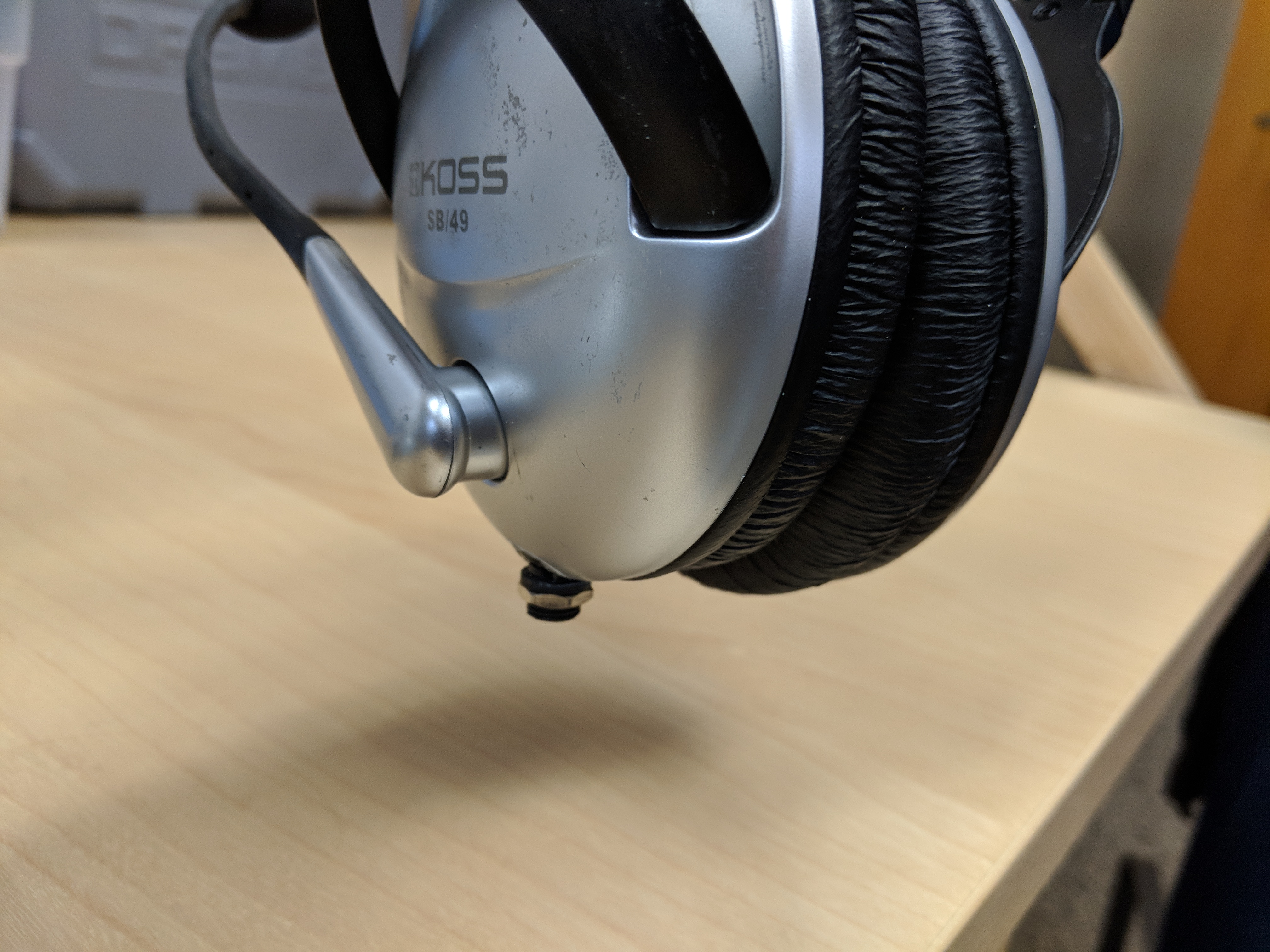
Results
Here’s the finished repair. Looks pretty good, right?
Repair process
To start with, I had to figure out how to open up the left-side headphone, where the current cable is attached. After lots of futzing, I removed the soft ear padding part by sliding it off very carefully. However, it turns out that this is not necessary, if you know where the hidden screws are located. In the image below, you can see me sliding the inner foam away to expose a screw hole. Use a small phillips screwdriver to remove the three screws (one indicated below, and two on the opposite side on both sides of the cable entry point).
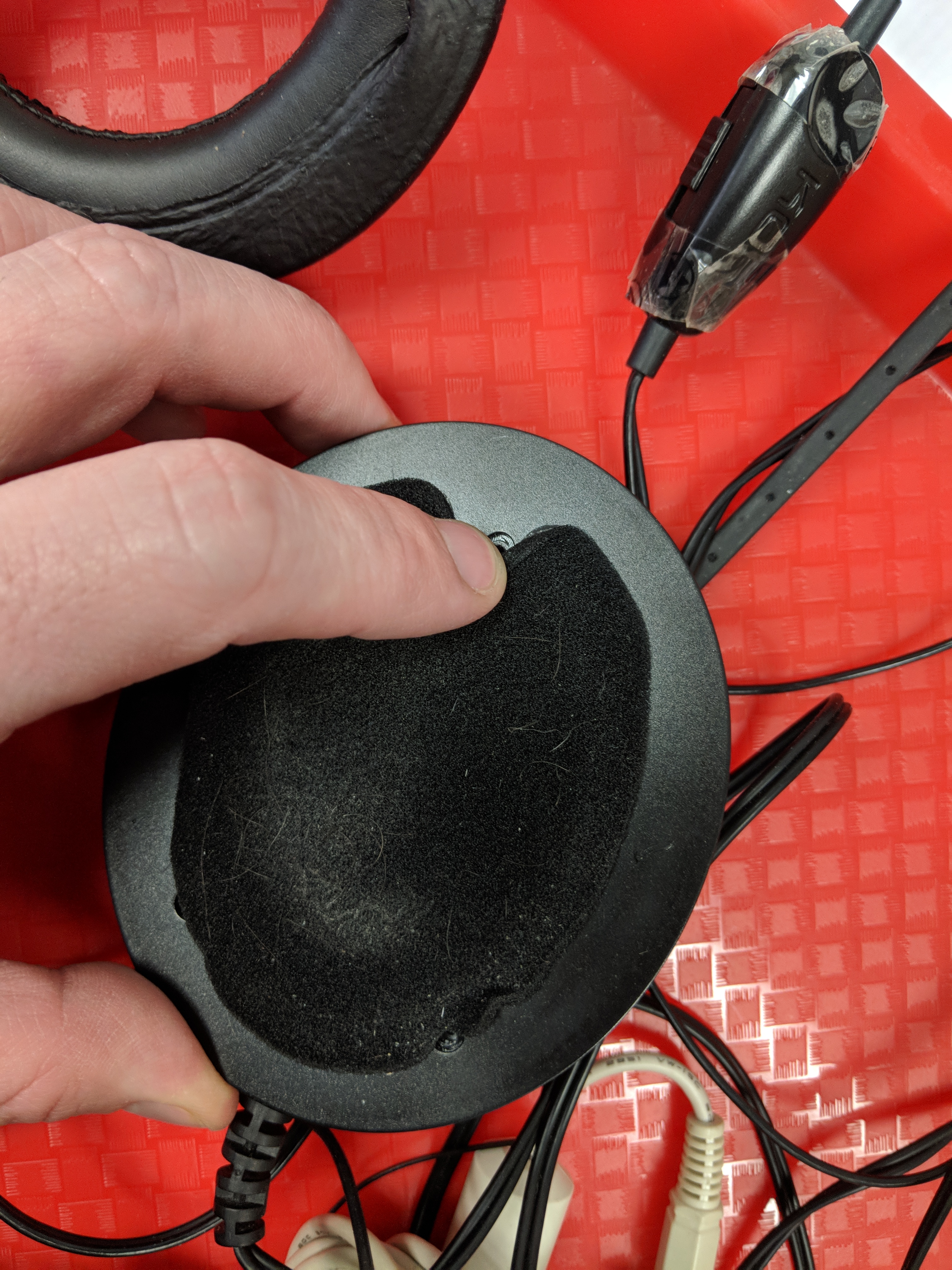
Peel back the foam covering a bit to expose the three screw holes (one by the finger, two below by the end with the to-be-removed cable).
You can also remove the two screws on the headband to disconnect the cup from the headband (aside from the small wire going to the right-side headphone), but I don’t think this is necessary.
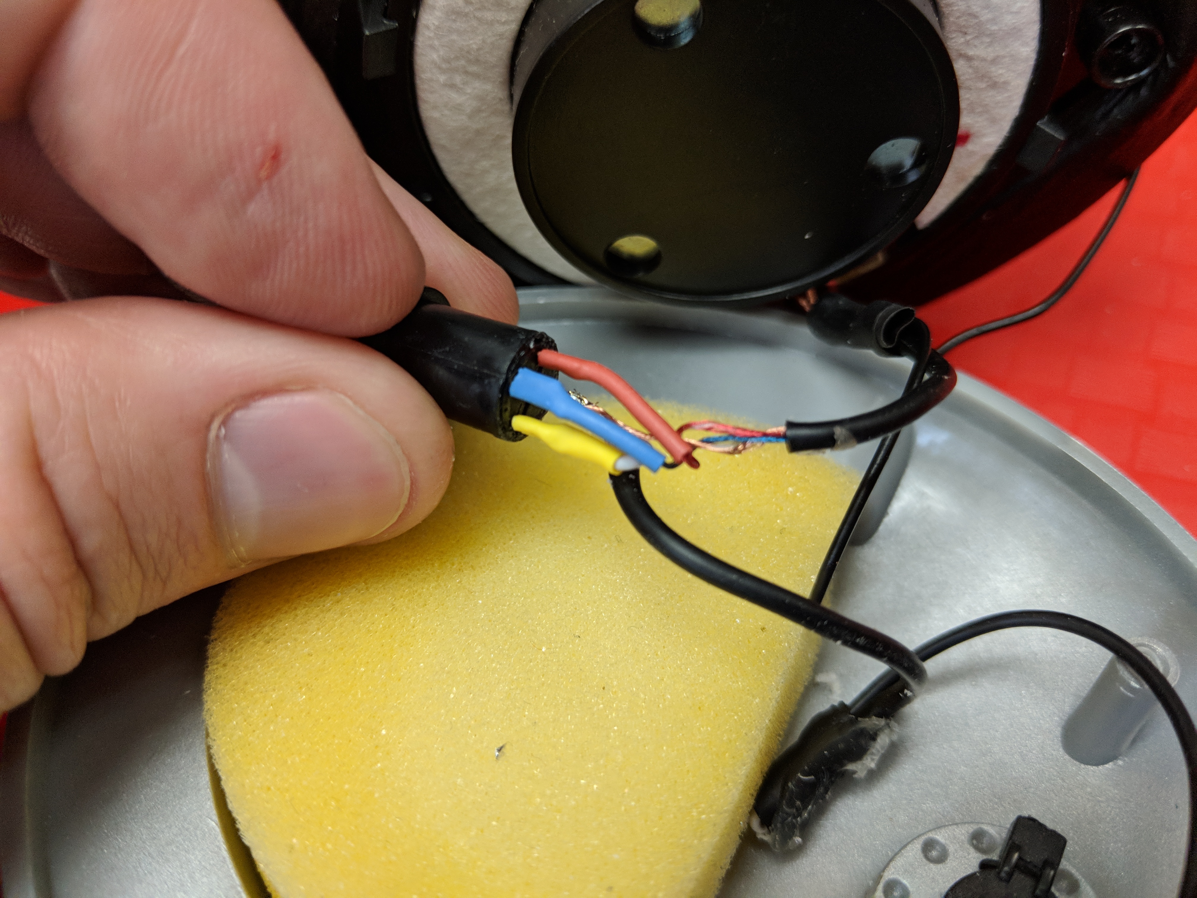
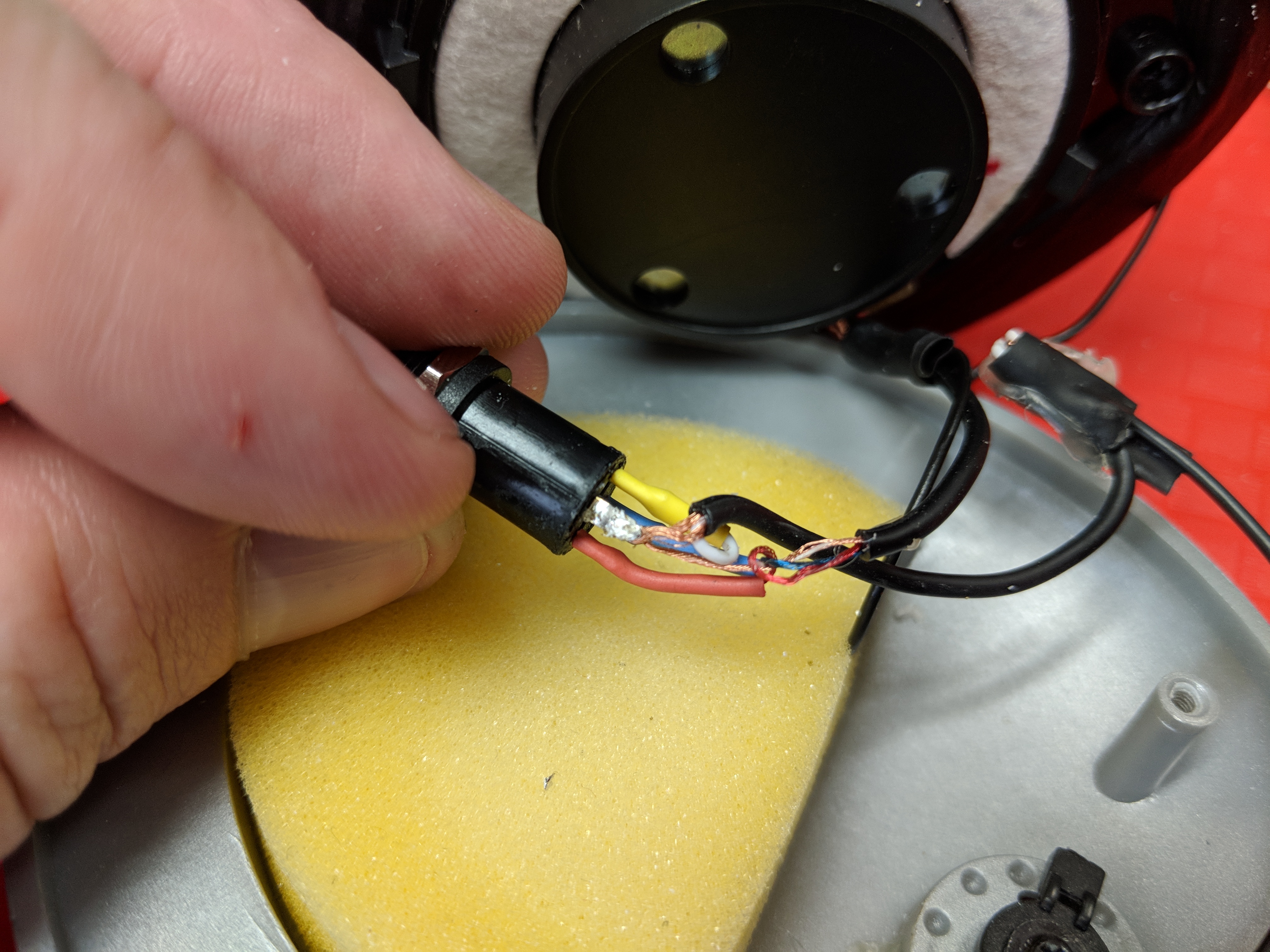
Once the cup is open we can inspect how the wires are connected to the two speakers and the microphone. My notes are shown below, but there are basically two cables entering the left headphone. The first is the speaker cable, which has red, blue, and bare copper wires inside. The bare copper wire is the “shield” connection on the TRS speaker plug, and is connected to both speakers as the common return path. The blue wire is connected to the left speaker, and the red wire is connected to the right speaker. The microphone cable has two conductors, the bare copper common wire and the mic signal in the white insulation.
Since my laptop and phone both have a four-conductor TRRS (Tip-Ring-Ring-Shield) cable socket, I decided to add a single TRRS socket to the headphones, hopefully in the same hole where the old cable was. I purchased a few of the “Jameco Valuepro PJ31640 4 Conductor TRRS Panel Mount Phone Jack, 3.5 mm” sockets. I followed the newer CTIA standard for TRRS plugs:
- Tip = socket pin 2 = left audio = blue wire
- Ring = socket pin 3 = right audio = red wire
- Ring = socket pin 4 = common ground = bare copper wires
- Shield = socket pin 1 = microphone signal = white wire
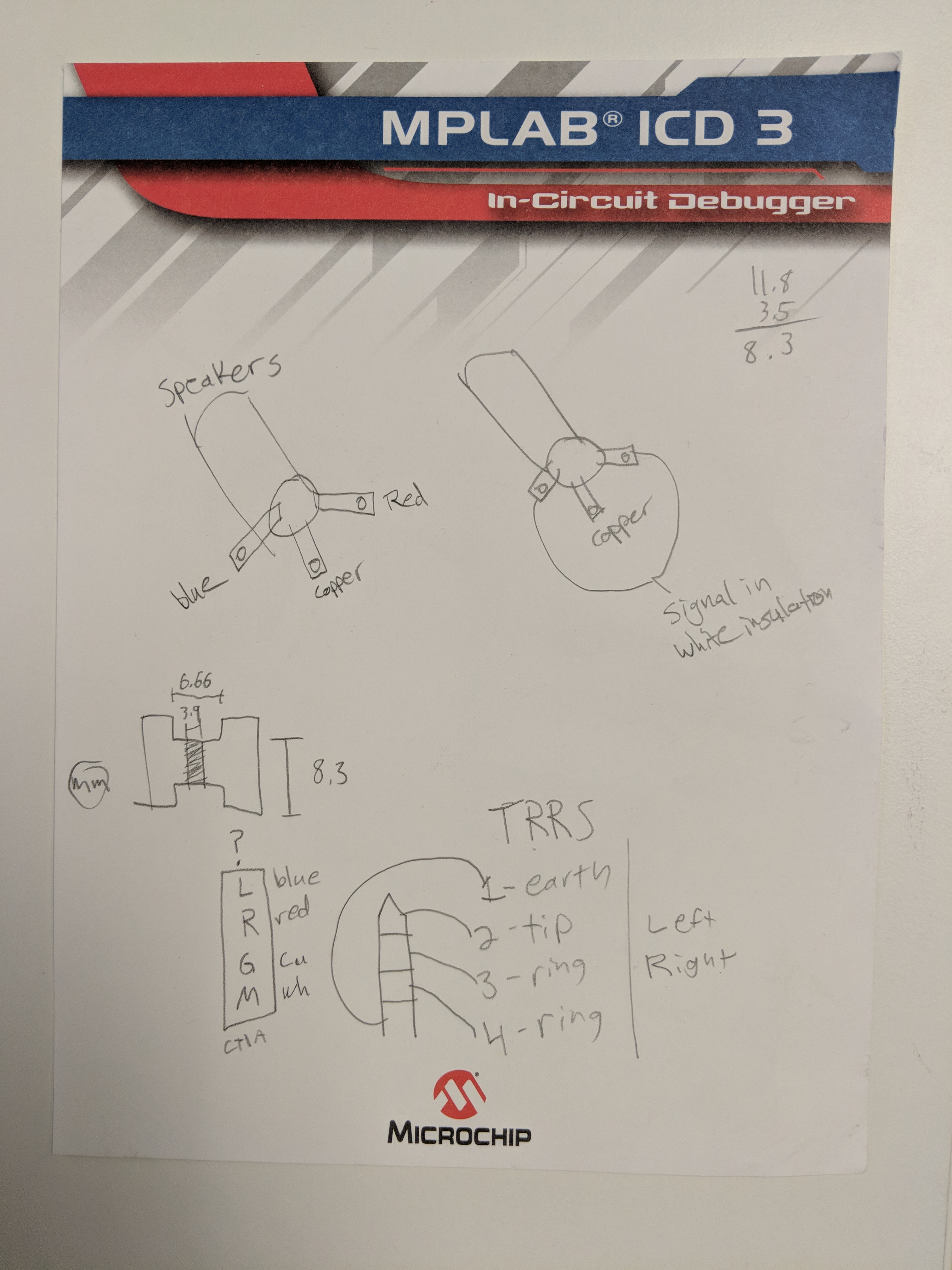
Notes about the connections between the speaker/mic plugs and the actual wires inside the left headphone. Below the “TRRS” heading, the word “earth” should really be “shield” as it’s used for the mic signal, not the common “earth” ground signal. (Ignore the drawing on the left side below the speaker wire diagram, it’s for a different project. Also ignore the simple subtraction in the upper-right corner.)
The next step was to cut the wires just past where they enter the headphone, to give us enough slack cable to work with. After deciding how to connect the four wires to the four pins of the TRRS socket (see plan above), we need to solder the wires to the socket pins. For the two bare copper ground signals (one for the speakers, one for the mic) I just soldered them both to the corresponding pin of the TRRS socket.
One thing to keep in mind when working with audio cables like this, is that the wires are typically coated with enamel, which will prevent you from soldering to it. You can quickly insert the tip of the enameled wire into a small flame to burn off the enamel, but be sure to blow-out the flame if the coating starts to burn.
I decided to add a bit of color-coordinated heatshrink tubing to ensure that the bare copper wire never made contact with any of the audio signals when everything gets jammed into the headphone and closed up. You can see two photos of that below.
Closing the headphone
With this kind of “panel mount” socket, it has a threaded barrel and nut that are designed to pinch the socket onto a faceplate. However, there wasn’t enough room inside the headphone to slide the socket all the way in, so I decided that the easiest option was to leave it sticking further out. I needed to file down the opening a little bit to ensure the socket fit snug in the slot. I then applied lots of superglue around the barrel of the socket, to ensure it was firmly attached. I then screwed it back together, trying to avoid gluing the two halves together (even if they did, the glue would be on the removable ear pad, so that’s 1. replaceable, and 2. easy to remove even if it’s glued to the socket).
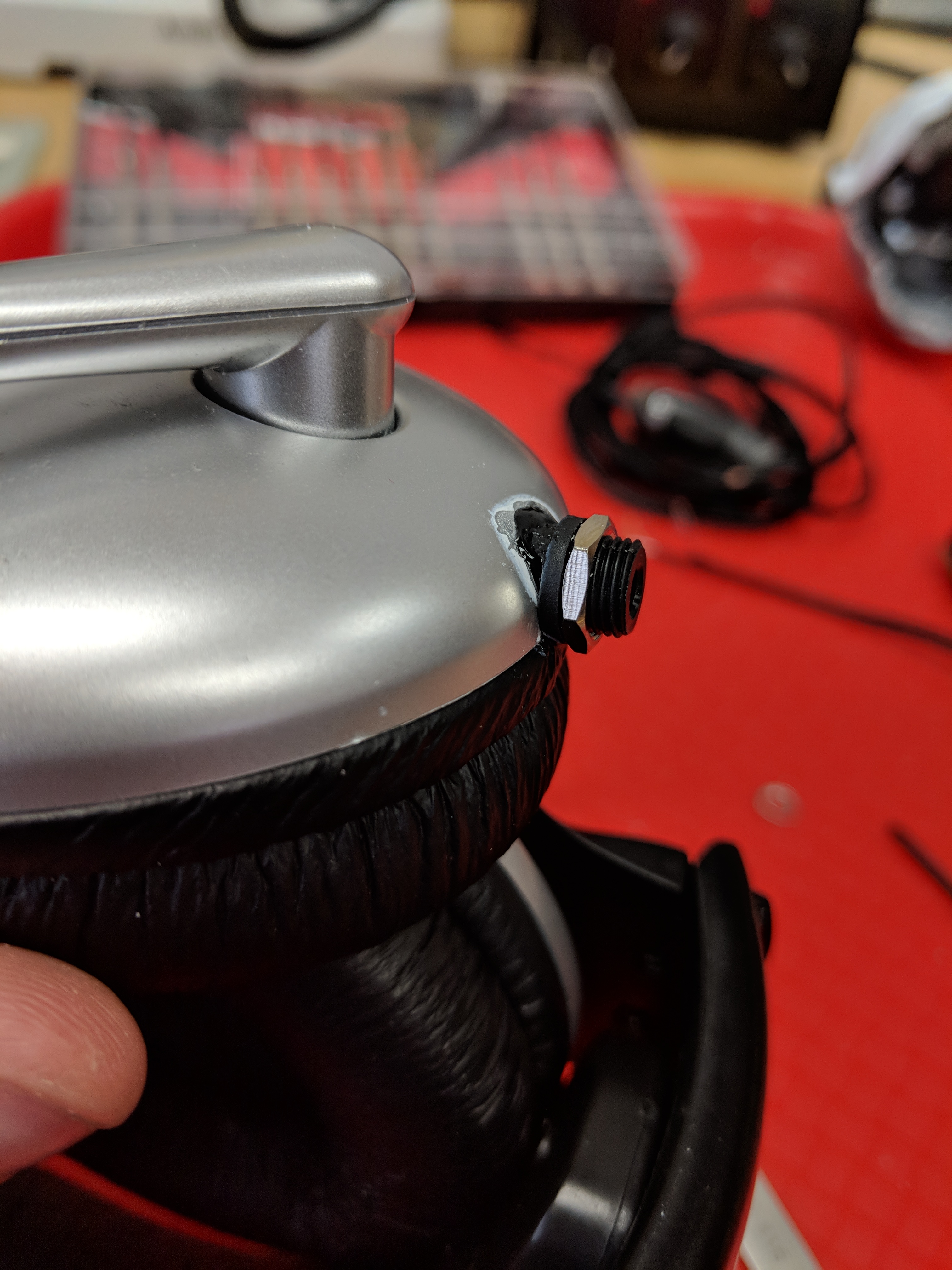
Normally the edge/face of the enclosure would be sandwiched between the metal hex nut and the extrusion of the black plastic socket that’s just to the left of the nut.
Superglue tends to deform and disfigure some types of plastic (see the white aura around the glue area) but I don’t mind.
Hope you find this interesting, and useful in case you need to make a similar repair of your own headphones someday!