Matthew Beckler's Home Page
:: :: :: :: :: ::
Java Heat Map
Convert Cadence Layout to SVG / PDF / PNG
Makefile -jX setting: How many concurent jobs is optimal?
Infinite Grid of Resistors
How to Start and Stop Folding@Home on OSX
Lego Rendering with POV-Ray
Class Scheduler
Lightsaber Rotoscoping Scripts

Handy Scripts
GPG Tips and Tricks
NCAA Basketball Tournament Data

Isometric Projection in Inkscape
Perspective Motivational Poster
SVG Drawings
SVG Circuit Symbols
Mysterious Textures
Using a voltage divider
Abstract: Microcontrollers are good at directly working with voltages in the range of 0 to 5 volts. When we want to measure voltages outside this range, we need to add hardware to translate and scale the input voltages down between 0 and 5 volts. For small current applications, we can use a voltage divider.
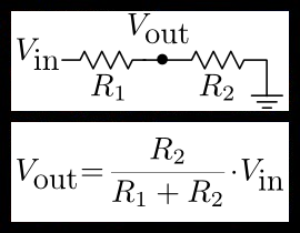
General Description:Most fans in a desktop computer run off 12 volts. If noise is an issues, the fan voltage can be lowered to run the fan at a slower (and quieter) speed. In this document, we will measure a voltage between 5 and 12 volts using a standard 5v microcontroller. A voltage divider will be used to scale the input voltage down between 0 and 5 volts. Go read about Voltage Dividers at Wikipedia. I have borrowed the schematic from the wikipedia page for reference here.
More Details: We will connect V_in on the voltage divider to the analog voltage we are going to be measuring. We connect V_out to the microcotroller's analog-to-digital pin. The only thing left to do is to find the values of R1 and R2.
Using the voltage-divider equation, we know that: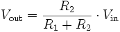
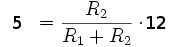
We look to our maximum input voltage to help us calculate R1 and R2. If V_in = 12v, then we want to ensure that V_out is below 5v:
We solve for R1:
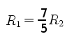
If we plug this relationship back into our original equation, we can find a relationship between V_in and V_out:
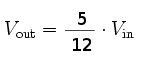
This relationship for R1 and R2 will work for an input voltage of 12v by reducing it down to 5v, but will it work for an input voltage of 5v? Using the previously found relationship, we find that for an input of 5v, we get an output of 2.08. Yes, this relationship between R1 and R2 will work for our purposes
How do we find actual resistor values? We know the relationship between R1 and R2, but now we need to find the actual resistor values. We need to select resistors that have enough resistance that they don't steal very much current from the main circuit. This is a measurement circuit, so we can use large resistors, on the scale of 10+ kilo-ohms. If we select R2 = 10K, then R2 is calculated to be 14K. They don't make 14K resistors, but they do make 15K resistors. Using 10K and 15K for our resistors, we can recalculate our overall equation, sometimes called a transfer function:
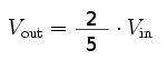
This revised transfer function will convert 12v to 4.8v, and 5v to 2v, still within our range of 0-5v. We decide on R1 = 10K and R2 = 15K.
Note: Keep in mind that most microcontroller's analog-to-digital convertors have very low input impedance (low resistance). This means that connecting your voltage divider to a microcontroller directly will likely negatively affect the measurement value. It would be better to connect a non-inverting buffer between the middle node of the voltage divider and your ADC input pin to reduce loading effects.


Copyright © 2004 - 2024, Matthew L. Beckler, CC BY-SA 3.0
Last modified: 2009-12-13 04:37:57 PM (EST)